Abstract
High-pressure vessel nozzle connections demand a joining method that minimizes weld seams, reduces inspection complexity, and maintains structural integrity under cyclic loading. The long weld neck flange addresses these demands through an extended tapered hub that integrates directly with the vessel shell. This analysis examines the geometric rationale, material selection criteria, dimensional standards, and installation practices that position this component as a technically superior solution for critical service conditions.
Engineers specifying components for petrochemical reactors, power generation boilers, and offshore processing equipment frequently encounter the question of when an integral flange outperforms a conventional welded assembly. The answer lies in understanding how load distribution, weld count reduction, and fatigue resistance interact in high-pressure environments.
Select any section to navigate directly:
1. Design Rationale Behind the Extended Hub Geometry
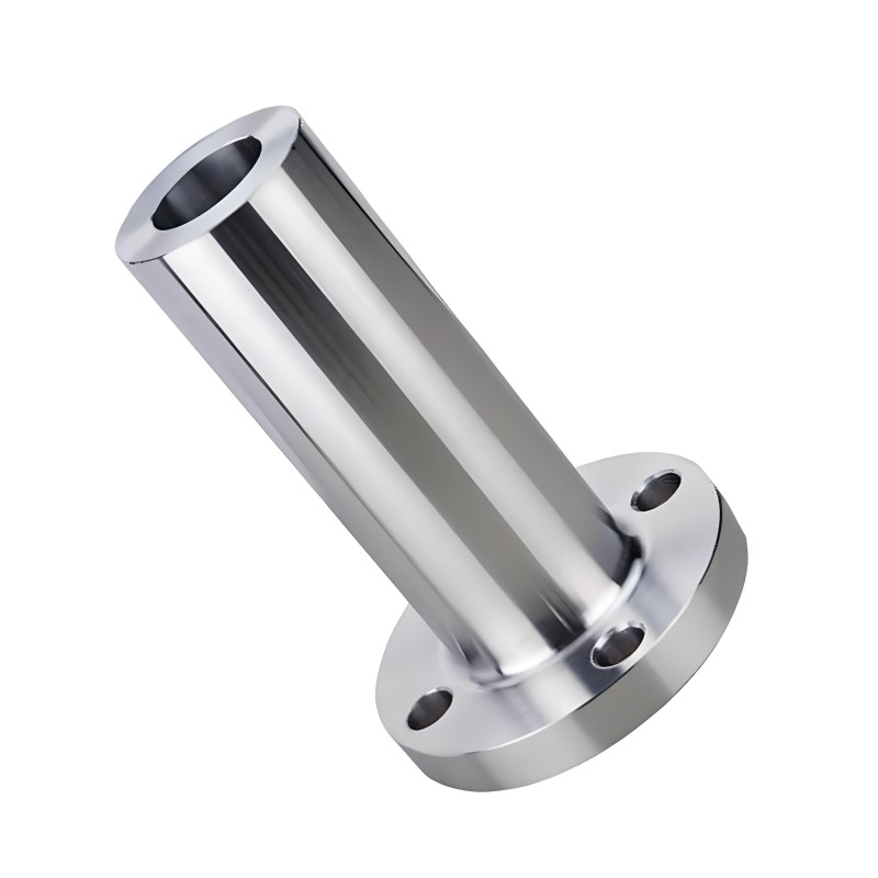
A standard weld neck flange features a tapered hub that transitions from the flange ring to the pipe bore. The long weld neck variant extends this hub significantly, creating a cylindrical neck that inserts directly into a vessel opening or nozzle shell. This geometric modification is not merely a dimensional variation; it fundamentally changes how forces transfer from the piping system into the pressure boundary.
When a piping system experiences thermal expansion, vibration, or pressure surges, the resulting bending moments concentrate at the connection point. The extended neck of a long weld neck flange distributes these moments over a longer section of the vessel wall, reducing localized stress concentrations that can lead to premature cracking. The gradual transition from the flange ring through the tapered hub to the vessel shell creates a smooth stress path, which is particularly valuable in cyclic service where fatigue life is a primary design consideration.
Key Geometric Features
- Extended cylindrical neck that inserts into the vessel opening, eliminating one circumferential weld.
- Tapered hub section that gradually transitions from flange thickness to neck diameter.
- Bore matching the vessel or pipe internal diameter to maintain uninterrupted flow.
- Available with raised face, flat face, or ring joint sealing surfaces.
The reduction of a weld seam carries operational benefits beyond structural performance. Each weld requires non-destructive examination, post-weld heat treatment in many alloys, and documentation. Eliminating one seam reduces these activities, shortens fabrication schedules, and removes a potential leak path. In hydrogen service or other hazardous media, this reduction in potential leakage points is a significant safety advantage.
2. Structural Advantages in High-Pressure Service
Pressure vessel design codes recognize the long weld neck flange as an integral component rather than a standard piping flange. This classification reflects the component's role in reinforcing the vessel opening while simultaneously providing a bolted connection for external piping. The extended neck acts as a reinforcing pad, compensating for the material removed to create the opening.
In high-pressure applications, the wall thickness of the vessel shell and the flange neck must be carefully matched. A mismatch creates a stiffness discontinuity that attracts bending stress. The long weld neck design allows engineers to specify a neck thickness that transitions gradually to the shell thickness, maintaining structural continuity. This is particularly important in thick-walled reactors and high-pressure separators where the shell thickness can exceed 100 mm.
| Design Aspect | Conventional Weld Neck Flange | Long Weld Neck Flange |
|---|---|---|
| Weld seams to vessel | Two (flange-to-pipe and pipe-to-vessel) | One (neck-to-vessel) |
| Stress distribution | Concentrated at pipe-to-vessel junction | Gradual through extended neck |
| Reinforcement of opening | Requires separate reinforcing pad | Integrated into neck geometry |
| Fatigue performance | Limited by weld toe stress concentration | Improved through smooth transition |
| Inspection scope | Two weld examinations | One weld examination |
The fatigue advantage is measurable. Cyclic loading from pressure fluctuations, thermal cycling, or mechanical vibration causes stress ranges that can initiate cracks at weld toes. The long weld neck flange moves the critical weld away from the high-stress region and provides a more gradual geometric transition, which reduces the stress concentration factor. For equipment subject to frequent startup and shutdown cycles, this improvement translates directly into extended service life.
3. Material Grades and Dimensional Standards
Material selection for a long weld neck flange follows the same logic as vessel shell material selection. The flange must possess sufficient strength at design temperature, adequate toughness at minimum design metal temperature, and compatibility with the process fluid. Carbon steel grades such as ASTM A105 are common for non-corrosive service, while stainless steels and nickel alloys are specified for corrosive environments.
Dimensional standards for this component are covered by ASME B16.5 for sizes up to NPS 24, though the standard explicitly notes that long weld neck flanges are not considered standard flanges within its scope. This distinction means that dimensions such as neck length and wall thickness are often specified by the purchaser or the vessel designer rather than being fixed by the standard. For larger sizes, ASME B16.47 or custom engineering drawings govern the geometry.
Common Material Specifications
- Carbon steel: ASTM A105, ASTM A350 LF2 for low-temperature service.
- Stainless steel: ASTM A182 F304, F304L, F316, F316L, F321, F347.
- Duplex and super duplex: ASTM A182 F51, F53, F55.
- Alloy steel: ASTM A182 F11, F22, F91 for elevated temperature service.
- Nickel alloys: Inconel 625, Incoloy 825, Monel 400 for severe corrosion.
The bore of the long weld neck flange must match the vessel or pipe internal diameter to avoid steps that could create turbulence or crevice corrosion. In some cases, the bore is machined after welding to achieve precise alignment. The sealing surface, whether raised face or ring joint, must meet surface finish requirements specified by the applicable gasket standard.
Wenzhou Shuangneng Valve Co., Ltd. manufactures long weld neck flanges in a range of materials and sizes, with capabilities for custom neck lengths and bore configurations to match specific vessel designs.
4. Installation, Inspection, and Quality Control
Installation of a long weld neck flange begins with verifying that the vessel opening dimensions match the flange neck outside diameter. The neck is inserted into the opening and positioned to achieve the correct projection beyond the vessel surface. Tack welds secure the component while maintaining alignment with the mating flange face.
The root pass of the weld is critical. For full penetration welds, back gouging or a consumable insert may be required to ensure complete fusion at the root. Welding procedures must account for the material grade and the thickness of both the neck and the vessel shell. Preheating and interpass temperature control are essential for alloy steels to prevent cracking.
After welding, non-destructive examination typically includes radiographic or ultrasonic testing of the circumferential weld. Dimensional checks verify flange face alignment, bolt hole orientation, and projection length. Pressure testing of the completed vessel confirms the integrity of the connection before commissioning.
Inspection Checklist
- Verify material certificates against specification requirements.
- Check neck outside diameter and wall thickness before fit-up.
- Confirm weld procedure qualification and welder certifications.
- Perform visual inspection of root pass and final weld cap.
- Conduct non-destructive examination per applicable code requirements.
- Measure flange face flatness, surface finish, and bolt hole alignment.
For critical service, additional testing may include hardness surveys, metallographic replication, or acoustic emission monitoring during pressure testing. The goal is to confirm that the long weld neck flange connection performs as designed throughout the equipment lifecycle.
5. Frequently Asked Questions
What is the primary difference between a long weld neck flange and a standard weld neck flange?
A standard weld neck flange has a short tapered hub designed to butt weld to a pipe. A long weld neck flange has an extended cylindrical neck that inserts directly into a vessel opening, eliminating the need for a separate pipe section and one circumferential weld.
Can a long weld neck flange be used in piping applications rather than vessel nozzles?
While technically possible, the extended neck is designed for insertion into a vessel shell or nozzle opening. Using it in standard piping would require cutting the neck to length, which negates the design advantages and may not comply with piping code requirements.
What determines the neck length of a long weld neck flange?
Neck length is typically specified by the vessel designer based on shell thickness, reinforcement requirements, and the desired distance from the vessel surface to the flange face. ASME B16.5 does not fix neck length for this component, so it is often a custom dimension.
How does the long weld neck flange improve fatigue life?
The extended neck provides a gradual transition from the flange ring to the vessel shell, reducing stress concentration at the weld. This smoother stress path delays crack initiation under cyclic loading compared to a conventional two-weld assembly.
Is post-weld heat treatment required after installing a long weld neck flange?
Requirements depend on the material grade, weld thickness, and applicable code. Carbon steel vessels may require post-weld heat treatment above certain thickness thresholds, while austenitic stainless steels generally do not. The vessel specification governs.